
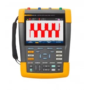
Fluke MDA-550-III Motor Drive Analyzer, 4 channel, 500 MHz

Part Number : MDA-550-III
Brand :
![Fluke]()
Perform extended harmonics measurements and simplify complex motor-drive troubleshooting with this powerful motor drive analyzer. Accurate and reliable, the analyzer features a built-in report generator that quickly and easily generates as-found and as-left reports.
View all
KWD 2,910.590
Description
Fluke MDA-550-III Offers Save time and eliminate the hassle of setting up complex measurements with the drive analyzer that simplifies the troubleshooting process. Select a test, and the step-by-step guided measurements will locate where to make voltage and current connections. The preset measurement profiles will capture all the data necessary for each critical motor-drive section—from the input to the output, the DC bus, and the motor itself. Features Key measurements: inverter output voltage, DC bus voltage and ripple voltage, harmonics, unbalance Three powerful test tools in one: motor-drive analyzer, waveform analyzer and recording data logger all in one Measure key motor-drive parameters including voltage, cur- rent, DC Bus voltage level and AC ripple, voltage and current unbalance and harmonics, voltage modulation, and motor shaft voltage discharges Perform extended harmonics measurements to identify the effects of low and high order harmonics on your electrical power system Conduct guided measurements for motor-drive input, DC bus, drive output, motor input and shaft measurements with graphical step-by-step voltage and current connection diagrams Use simplified measurement setup with preset measurement profiles to automatically trigger data collection based on the chosen test procedure Create reports quickly and easily that are perfect for documenting troubleshooting and collaborative work with others Measure additional electrical parameters with full 500 MHz oscilloscope, meter and recording capability for complete range of electrical and electronic measurement on industrial systems Highest safety rating - 600 V CAT IV/1000 V CAT III rated for use at the service entrance and downstream Applications Industrial automation HVAC/R Motor repair Discrete or process based industrial manufacturing Waste water treatment Oil and gas maintenance Drive Input Measure input voltage and current to quickly see whether values are within acceptable limits by comparing the drive's nominal rated voltage to the actual supplied voltage. Then, check the input current to determine if the current is within the maximum rating and the conductors are suitably sized. You can also check whether the harmonic distortion is within an acceptable level by visually inspecting the waveform shape or by viewing the harmonics spectrum screen which shows both the total harmonic distortion and individual harmonics. Voltage and Current Unbalance Check the voltage unbalance at the input terminals so you can ensure the phase unbalance is not too high (>6 to 8%), and that the phase rotation is correct. You can also check the current unbalance, as excessive unbalance may indicate a drive rectifier problem. Extended Harmonic Measurements Excessive harmonics are not just a threat to your rotating machines but also to other equipment connected to the electrical power system. It provides the ability to discover the harmonics of the motor-drive but can also discover the possible effects of inverter switching electronics. It has three harmonic ranges, 1st to 51st Harmonics, 1 to 9 kHz and 9 to 150 kHz giving the ability to detect any harmonic pollution problems. DC Bus In a motor-drive the conversion of AC to DC inside the drive is critical, having the correct voltage and adequate smoothing with low ripple is required for the best drive performance. High ripple voltage may be an indicator of failed capacitors or incorrect sizing of the connected motor. The record function can be used to check DC bus performance dynamically in the operating mode while a load is applied. Drive Output Check the output of the drive focusing both on voltage to frequency ratio (V/F), and voltage modulation. When high V/F ratio measurements are experienced, the motor may overheat. With low V/F ratios, the connected motor may not be able to provide the required torque at the load to sufficiently run the intended process. Voltage Modulation Measurements of the Pulse Width Modulated signal are used to check for high voltage peaks which can damage motor winding insulation. The rise time or steepness of impulses is indicated by the dV/dt reading (rate of voltage change over time), this should be compared to the motor's specified insulation. The measurements can also be used to measure switching frequency to identify whether there is a potential issue with electronic switching, or with grounding, where the signal floats up and down. Motor Input Ensuring that voltage is being supplied at the motor input terminals is key, and the selection of cabling from drive to the motor is critical. Incorrect cabling selection can result in both drive and motor damage due to excessive reflected voltage peaks. Checking that the current present at the terminals is within the motor rating is important as over current condition could cause the motor to run hot, decreasing the life of the stator insulation which can result in the early failure of the motor. Motor Shaft Voltage Voltage pulses from a variable speed drive can couple from a motor's stator to its rotor, causing a voltage to appear on the rotor shaft. When this rotor shaft voltage exceeds the insulating capacity of the bearing grease, flashover currents (sparking) can occur, causing pitting and fluting of the motor bearing race, damage that can cause a motor to fail prematurely. It is supplied with carbon fiber brush probe tips that can easily detect the presence of destructive flashover currents, while the impulse amplitude and count of events will enable you to take action before failure occurs. The addition of this accessory and capability of the MDA-550 allows you to discover potential damage without investing in expensive permanently installed solutions. Step-by-Step Guided Measurements Ensure You Have the Data You Need, When You Need It Designed to help you quickly and easily test and troubleshoot typical problems on three-phase and single-phase inverter type motor-drive systems. The on-screen information, and step-by-step setup guidance make it easy to con- figure the analyzer and get the drive measurements you need to make better maintenance decisions, fast. From power input to the installed motor, it provides the measurement capability for the fastest motor-drive troubleshooting. Reporting and Analysis Simplifies the process of gathering data and writing test reports with a built-in report generator. At each test point or measurement there is the option to create, update or modify a report. Simply press ‘SAVE TO REPORT' and select the appropriate screens to save into a text based report file. By performing the step-by-step guided measurements a comprehensive report can be created directly from the instrument to document the entire troubleshooting process. Input the report name. The single report encompasses all recorded measurements and can easily be shared with other users and used for motor- drive benchmarking, and for comparing data now and in the future. Using Fluke Thermal Imaging to Troubleshoot Motors & Drives Infrared cameras, also called thermal imagers, are useful for troubleshooting motor problems as well as for monitoring motor condition for preventative maintenance in power generation, manufacturing and commercial plants. Thermal images of motors reveal their operating condition as indicated by surface temperature. Such condition monitoring is important as a way to avert many unexpected motor malfunctions in systems that are critical to manufacturing. The onset of motor failures can often be detected by a variety of techniques, including vibration, ultrasound and thermal imaging. In this article, we cover why use thermal imaging and what to scan, as well as some notes on what to look for, including shaft misalignment. Read the Article Facilities Maintenance Challenges and the Fluke Solutions Facilities maintenance professionals face a wide range of challenges, from electrical and mechanical equipment uptime to overall safety concerns. It’s critical to maintain facilities and the associated assets at peak performance. Let's review the issues faced by maintenance managers, IT support, and electrical/mechanical technicians. Along with the Fluke solutions that offer to save you time and money while increasing efficiency and safety. Fluke makes reliable, rugged and accurate tools to maintain electromechanical systems, motors, pumps, electrical distribution systems and more to keep your world up and running. Learn More
Specifications
- 1 mV
- 10 mV
- 999 counts
- 1100 counts
- 800 counts
- 999 counts
Related Products
![]()
![Image Brand]()
Fluke 325 True RMS Clamp Meter, AC/DC
Part Number : 325
![]()
![Image Brand]()
Fluke 325 CAL True RMS Clamp Meter with calibration certificate, 400 A AC/DC
Part Number : 325 CAL
![]()
![Image Brand]()
Fluke 787B CAL Process Meter with calibration certificate, 1,000 V
Part Number : 787B CAL
![]()
![Image Brand]()
Fluke 789 CAL Process Meter with calibration certificate, 24 V loop
Part Number : 789 CAL
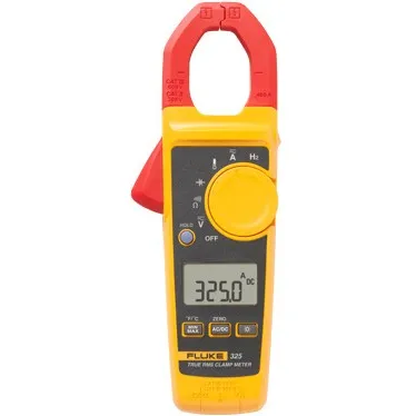
Fluke 325 True RMS Clamp Meter, AC/DC
Part Number : 325

Fluke 325 CAL True RMS Clamp Meter with calibration certificate, 400 A AC/DC
Part Number : 325 CAL
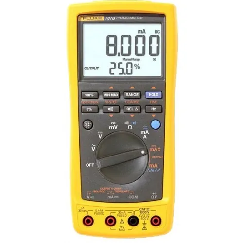
Fluke 787B CAL Process Meter with calibration certificate, 1,000 V
Part Number : 787B CAL

Fluke 789 CAL Process Meter with calibration certificate, 24 V loop
Part Number : 789 CAL
LEGAL DISCLAIMER
All products are 100% genuine and legally purchased from authorized sources. Indspare is not an authorized dealer, agent or affiliate of any of the designers, brands, or manufacturers, the products of which are offered for sale on www.indspare.com. All trademarks, brand names, and logos mentioned are used for identification purposes only and are registered trademarks of their respective owners who reserve the rights of ownership. The use of trademark, brand name or product on our website is not intended to suggest that the company, trademark or brand is affiliated to or endorses our website.