
Fluke FEV150 EV Charging Station Analyzer Kit with type 1 plug

Part Number : FEV150/TY1
Brand :
![Fluke]()
Perfect for field technicians who value safety, ease of use, and portability, this EV charging station analyzer provides predetermined test plans and pass/fail indicators, allowing thorough and efficient testing without needing multiple tools. In addition, this kit comes with an American-compatible type 1 plug.
View all
KWD 929.690
Description
Fluke FEV150/TY1 OffersTest the safety and functionality of AC electrical vehicle charging stations with the all-in-one tool that is safe, portable, and efficient.The FEV150 is a complete solution for safety and performance testing of AC EV charging stations with Type 1 (J1772) or Tesla-type connectors. Deliver uptime reliability with Fluke's next generation of EV Charging test solutions, designed for technicians to perform and document multiple tests safely, quickly, and efficiently without carrying multiple tools.The FEV150 EV Charging Station Analyzer is compliant with J1772 standards.FeaturesProvides critical protective ground testing of the stationComprehensive EVSE test tool with UI to support all critical performance and safety tests of AC EV charging stationsAdvanced functionality with Auto CP waveform analysisOnly tool to support all AC EVSE connectors availablePass/Fail indications on all measurement resultsGFCI testing for 6 and 20 mA GFCI circuitsPE (protective) earth pre-test to ensure no dangerous voltage is presentVisual inspectionGFCI trip testNominal voltageAuto control pilot (CP) with waveform analysisError testingProximity pilotManual control pilotAdvanced GFCI testColor LCD display: On-screen instructions provide an easy walkthrough of tests with a pass/fail indication on all test resultsEasily analyze EV charging performance: Auto control pilot simulates various charging states with on-screen feedback of nominal results and waveform analysisFunction selectionPE pre-test to check if hazardous voltage is presentPress up/down and left/right arrow keys to select features on the displayApplicationsCharging station safety testingCharging station performance testingCharging station troubleshooting/repair
Downloads
Specifications
- Display range: 40 to 70 Hz Measurement range: 40 to 70 Hz Operational error: ±0.20 Hz
- Display range: 0.9 to 1.1 kHz (A, B, C, D) Measurement range: 0.9 to 1.1 kHz Operational error: 0.1% (based on voltage) Nominal values: RIN: 1 MΩ 0.9 to 1.1 kHz UCP+ >2 V, UCP- <-2 V
Related Products
![]()
![Image Brand]()
Fluke 325 True RMS Clamp Meter, AC/DC
Part Number : 325
![]()
![Image Brand]()
Fluke 325 CAL True RMS Clamp Meter with calibration certificate, 400 A AC/DC
Part Number : 325 CAL
![]()
![Image Brand]()
Fluke 787B CAL Process Meter with calibration certificate, 1,000 V
Part Number : 787B CAL
![]()
![Image Brand]()
Fluke 789 CAL Process Meter with calibration certificate, 24 V loop
Part Number : 789 CAL
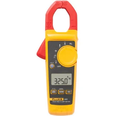
Fluke 325 True RMS Clamp Meter, AC/DC
Part Number : 325

Fluke 325 CAL True RMS Clamp Meter with calibration certificate, 400 A AC/DC
Part Number : 325 CAL
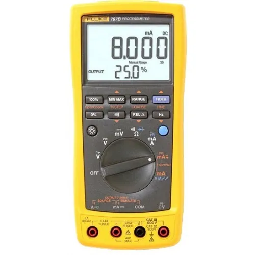
Fluke 787B CAL Process Meter with calibration certificate, 1,000 V
Part Number : 787B CAL

Fluke 789 CAL Process Meter with calibration certificate, 24 V loop
Part Number : 789 CAL
LEGAL DISCLAIMER
All products are 100% genuine and legally purchased from authorized sources. Indspare is not an authorized dealer, agent or affiliate of any of the designers, brands, or manufacturers, the products of which are offered for sale on www.indspare.com. All trademarks, brand names, and logos mentioned are used for identification purposes only and are registered trademarks of their respective owners who reserve the rights of ownership. The use of trademark, brand name or product on our website is not intended to suggest that the company, trademark or brand is affiliated to or endorses our website.