
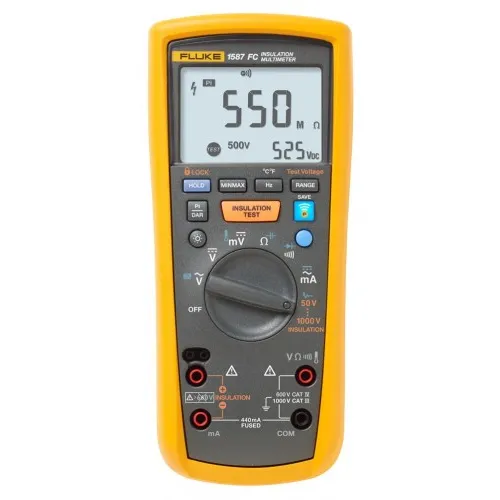
Fluke 1587FC Insulation Multimeter

Part Number : 1587 FC
Brand :
![Fluke]()
Ideal for troubleshooting and preventative maintenance, this insulation multimeter comes in a compact, handheld design, and features True RMS capabilities. Additionally, this tool is compatible with the Fluke Connect app, which allows the user to see and share measurement results wirelessly with their smartphone or tablet.
View all
KWD 322.090
Description
Fluke 1587FC Offers The high-performance 2-in-1 insulation digital multimeter This insulation multimeter is the combination of a digital insulation tester that comes supplied with a full-featured, True RMS digital multimeter in a single compact, handheld unit, which enables maximum versatility for troubleshooting and preventative maintenance. Features PI/DAR timed ratio tests Live circuit detection prevents insulation test if voltage >30 V is detected for added user protection VFD low-pass filter for accurate motor drive measurements Auto-discharge of capacitive voltage for added user protection Insulation test of 0.01 M? to 2 G? Insulation test voltages of 50, 100, 250, 500 V for many applications AC/DC voltage, DC millivolts, AC/DC milliamps, resistance (?), continuity Capacitance, diode test, temperature, Min/Max, frequency (Hz) Auto power off to save battery power CAT III 1000 V, CAT IV 600 V measurement category Large display with backlight Safety first. Keep yourself out of harm's way by monitoring your test measurements remotely Prove your job is done right by quickly seeing and sharing measurement results wirelessly with your smartphone Quickly find problems by saving and comparing measurements over time on a wireless device Keep yourself safe. Find hidden problems faster. Put the paperwork down. Fluke Connect and this insulation multimeter helps you identify tough problems, fix, and wirelessly communicate your work quickly and easily - all at a safe distance. Add diagnostics with Fluke Connect Fluke Connect is enabled so you can download the free application to your smartphone and gain additional functions, including: Safety first. Keep yourself out of harm's way by monitoring your test measurements remotely Prove your job is done right by quickly seeing and sharing measurement results wirelessly with your smartphone Quickly find problems by saving and comparing measurements over time on a wireless device PI/DAR timed ratio tests with TrendIt™ graphs to identify moisture and contaminated insulation problems faster Memory storage through Fluke Connect that saves measurements to your phone or the cloud and eliminates the need to write down results. Reduces errors and saves data for historical tracking over time Temperature compensation to establish accurate baselines and relevant historical comparisons Historical tracking and trending of assets to identify insulation degradation over time and allow real-time decisions to be made in the field with Fluke Connect® Assets (sold separately) Provides memory storage through Fluke Connect Measurements to eliminate the need to write down results Includes live circuit detection to prevent insulation test if voltage >30 V is detected Provides automated temperature compensation to establish accurate baselines Incorporates VFD low-pass filter for accurate variable frequency motor drive measurements Includes auto-discharge of capacitive voltage for added user protection Measures AC/DC voltage, DC millivolts, AC/DC milliamps, resistance, and continuity Includes capacitance, diode test, temperature, min/max, frequency measurements and insulation test smoothing reading 6 Tips for effective insulation testing 1 Disconnect any electronic devices like motor drives, PLC’s, transmitters, etc. before performing insulation testing. Electronics can be damaged by applying higher than normal voltage. 2 The effect of temperature should be considered - it is recommended that tests be performed at a standard conductor temperature of 20 °C (68 °F) or that a temperature baseline is established while compensating future readings by using a DMM with a probe or an infrared thermometer. 3 Select a test voltage appropriate for the insulation being tested. The objective is to stress the insulation but not to over-stress it. When in doubt, use a lower test voltage. It’s usually appropriate to test insulation at twice the voltage it normally sees: for example 460 V to 600 V rated equipment is often tested at 1000 V. 4 When using an insulation tester, leave the leads connected when you stop the test. The insulation tester can discharge any residual test voltage. 5 Conductors that are close to each other have a normal capacitance. This will cause an insulation resistance reading to start low and increase steadily until it stabilizes. This type of increase is normal, but if the reading jumps violently down and up again this indicates arcing. 6 Although the current is tightly limited, an insulation tester can generate sparks and minor but painful burns. The unexpected surprise can cause an operator to jerk away. As always, work away from live systems and use safe work practices when working overhead. Insulation Resistance Testing Solutions Using Fluke Thermal Imaging to Troubleshoot Motors & Drives Infrared cameras, also called thermal imagers, are useful for troubleshooting motor problems as well as for monitoring motor condition for preventative maintenance in power generation, manufacturing and commercial plants. Thermal images of motors reveal their operating condition as indicated by surface temperature. Such condition monitoring is important as a way to avert many unexpected motor malfunctions in systems that are critical to manufacturing. The onset of motor failures can often be detected by a variety of techniques, including vibration, ultrasound and thermal imaging. In this article, we cover why use thermal imaging and what to scan, as well as some notes on what to look for, including shaft misalignment. Read the Article
Downloads
Specifications
- 600 mV 6 V 60 V 600 V 1000 V
- 6 V DC 60 V DC 600 V DC 1000 V DC
- 600 mV DC
- 400 mA
- 60 mA
- 600 Ω 6 kΩ 60 kΩ 600 kΩ 6 MΩ 50 MΩ
- 99.99 Hz 999.9 Hz 9.999 kHz 99.99 kHz
- 1000 nF 10.00 µF 100.0 µF 9999 µF
- -40 to 998°F (-40 to 537°C)
- 0.1 mV 0.001 V 0.01 V 0.1 V 1 V
- 0.001 V 0.01 V 0.1 V 1 V
- 0.1 mV
- 0.1 mA
- 0.01 mA
- 0.1 Ω 0.001 kΩ 0.01 kΩ 0.1 kΩ 0.001 MΩ 0.01 MΩ
- 0.01 Hz 0.1 Hz 0.001 kHz 0.01 kHz
- 1 nF 0.01 µF 0.1 µF 1 µF
- 0.1°F (0.1°C)
- ±(0.09% + 2) ±(0.09% + 2) ±(0.09% + 2) ±(0.09% + 2)
- ±(0.1 + 1)
- ±(1.5% + 2)1
- ±(0.2% + 2)
- ±(0.1% + 1) ±(0.1% + 1) ±(0.1% + 1) ±(0.1% + 1)
- ±(1.2% + 2) ±(1.2% + 2) ±(1.2% ± 90 counts) ±(1.2% ± 90 counts)
- 1000 RMS or DC
- 1000 V RMS
- <1.1 mA
- 1.0 mA typical
Related Products
![]()
![Image Brand]()
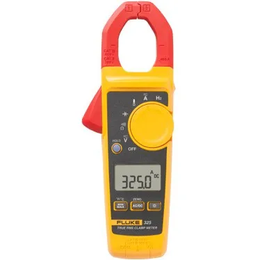
Fluke 325 True RMS Clamp Meter, AC/DC
Part Number : 325
![]()
![Image Brand]()
Fluke 325 CAL True RMS Clamp Meter with calibration certificate, 400 A AC/DC
Part Number : 325 CAL
![]()
![Image Brand]()
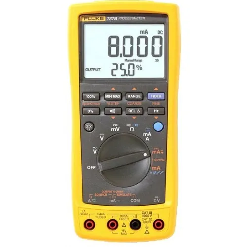
Fluke 787B CAL Process Meter with calibration certificate, 1,000 V
Part Number : 787B CAL
![]()
![Image Brand]()
Fluke 789 CAL Process Meter with calibration certificate, 24 V loop
Part Number : 789 CAL
Fluke 325 True RMS Clamp Meter, AC/DC
Part Number : 325

Fluke 325 CAL True RMS Clamp Meter with calibration certificate, 400 A AC/DC
Part Number : 325 CAL
Fluke 787B CAL Process Meter with calibration certificate, 1,000 V
Part Number : 787B CAL

Fluke 789 CAL Process Meter with calibration certificate, 24 V loop
Part Number : 789 CAL
LEGAL DISCLAIMER
All products are 100% genuine and legally purchased from authorized sources. Indspare is not an authorized dealer, agent or affiliate of any of the designers, brands, or manufacturers, the products of which are offered for sale on www.indspare.com. All trademarks, brand names, and logos mentioned are used for identification purposes only and are registered trademarks of their respective owners who reserve the rights of ownership. The use of trademark, brand name or product on our website is not intended to suggest that the company, trademark or brand is affiliated to or endorses our website.